Auslogics Boostspeed 4.1.4.135 Crack
Auslogics boostspeed 4.1.4.135 serial numbers are presented here. No registration. The access to our data base is fast and free, enjoy. Serial Realm. the realm of all.
Found 6 results for Auslogics Boostspeed 4.1.4.135 Incl. Full version downloads available, all hosted on high speed servers.
Auslogics boostspeed 4.1.4.135.rar. File QR Code. Site Links. Home Premium Link to Us Search. Help. Support FAQ Quick Tour Features Contact Us. About. Company.
Boostspeed 4.1.1, 12 records found:
Auslogics Boostspeed 5.1.4.135 serialAuslogics Boostspeed 4.1.4.135 serial makerAuslogics Boostspeed 4.1.2.116 serial number makerAuslogics Boostspeed 4.1 keygenAuslo Gics Boostspeed 4.1.4.135 crackAuslogics Boostspeed 4.1.4 crackAuslogics Boostspeed 4.1.2 serials generatorAuslogics Boostspeed V 4.1.3.12 serial makerAuslogics Boostspeed 4.1.3.121 keygenAuslogics Boostspeed 4.1.0.98 crackAuslogics Boostspeed 4.1.4.133 keygenAuslogics Boostspeed 4.1.1.105 serial keygen
Probably you can find Boostspeed 4.1.1 key gen here
Doesn t work. Look for Boostspeed 4.1.1 SERIAL here
Nothing found. Try to download Boostspeed 4.1.1 keygen from Media Library.
Download Boostspeed 4.1.1 serial number, keygen, crack or patch
AusLogics BoostSpeed 4.1.4.135 Patch By HSN.C3r-Under SEH Team keygen as Download AusLogics BoostSpeed 4.1.4.135 Patch By HSN.C3r-Under SEH Team crack.

About download Auslogics boostspeed 4 1 4 135 rus keygen. Days ago. 6 01 086 FlashPeak SlimBrowser 6.01.083 RuS Portable Letitbit Turbobit. Категория.

Aug 22, 2015. Internet Download Manager 6. INFORMATION. Download files for your computer that tweak, repair, auslogics boostspeed 4 1 4 135.

Auslogics Boostspeed 4.1.4.135 Incl
DownloadKeeper.com provides 24/7 fast download access to the most recent releases. We currently have 275,848 direct downloads including categories such as: software, movies, games, tv, adult movies, music, ebooks, apps and much more. Our members download database is updated on a daily basis.
Take advantage of our limited time offer and gain access to unlimited downloads for 3. That s how much we trust our unbeatable service. This special offer gives you full member access to our downloads. Take the DownloadKeeper.com tour today for more information and further details.
Auslogics Boostspeed 4.1.4.135 Incl Information
Auslogics Boostspeed 4.1.4.135 Incl was added to DownloadKeeper this week and last updated on 21-Jan-2016. New downloads are added to the member section daily and we now have 275,848 downloads for our members, including: TV, Movies, Software, Games, Music and More.
It s best if you avoid using common keywords when searching for Auslogics Boostspeed 4.1.4.135 Incl. Words like: crack, serial, keygen, free, full, version, hacked, torrent, cracked, mp4, etc. Simplifying your search will return more results from the database.
Helpful Information: What is a Keygen.
The word keygen means a small program that can generate a cd key, activation number, license code, serial number, or registration number for a piece of software. Keygen is a shortcut word for Key Generator. A keygen is made available through crack groups free to download. When writing a keygen, the author will identify the algorithm used in creating a valid cd key. Once the algorithm is identified they can then incorporate this into the keygen. If you search a warez download site for auslogics boostspeed 4.1.4.135 incl keygen, this often means your download includes a keygen.
Patch Cable Wire Diagram
LANshack.com was the very first ecommerce website to offer free online tutorials for cable connections. To say that our articles have been popular over the span of many years would be an understatement. But time marches on and we now have three major updates. For one, we have updated this very popular tutorial, and two, we now have a video tutorial to go with it. But most importantly, we have now developed a totally new system for termination cables called the QuickTreX PRO System.
Wow. After over 10 Years of working with cables, tools and connectors, and after keeping on top of our tool, cable, and connector suppliers, we have put it all together to formulate this system for the present a future of cabling components. What does all this mean to the consumer. Compatibility, Reliability, Dependability, ease of use and virtually fool-proof and repeatable results.
Due to an overwhelming response to our category 5 6 tutorial, and many requests for information and wiring diagrams of straight through and crossover cross-pinned patch cords, I have made this informational page and technical video. On this page, we will cover making patch cords, and other technical and non-technical issues relating to category 5 and 6 patching and connectivity from device to device. Below, you will find the diagrams for 568A, 568B, and crossover patch cables. I suggest that you read on, past the diagrams for some very useful and important information.
As always, there continues to be Controversies over standards and practices regarding the use and making of patch cords, and UTP cable in general. Please see our section below titled: Controversies and Caveats : Category 5, 5E, and Cat 6 Patch Cables. I hope that you will find it interesting and informative.
Notes for wiring diagrams above:
1. For patch cables, 568-B wiring is by far, the most common method.
2. There is no difference in connectivity between 568B and 568A cables. Either wiring should work fine on any system. see notes below
3. For a straight through cable, wire both ends identical.
4. For a crossover cable, wire one end 568A and the other end 568B.
5. Do not confuse pair numbers with pin numbers. A pair number is used for reference only eg: 10BaseT Ethernet uses pairs 2 3. The pin numbers indicate actual physical locations on the plug and jack.
Patch Cable Assembly Instructions
1. Cut the cable to the length that you will need.
If you are planning to use boots, this would be a good time to slip them on.
Place each boot facing out on the cable.
2. Skin the cable about 1.5down.
For fast and dependable skinning we recommend our QuickTreX EZ Cable stripper.
3. Remove all of the twists in the cables pairs.
TEC-TIP: Use a piece of the removed insulation to make it easy to remove the twists from each pair.
Un-twist each pair, and straighten each wire between the fingers.
4. Cat 6 cable has a center spine that needs to be removed.
Pull on the spine and fold the pairs back.
Then cut the spine as close to the cables end as possible.
5. Place the wires in the order of one of the two diagrams shown above 568B or 568A.
Here we have chosen the 568B diagram which is by far the most popular.
If you are unsure, go with the 568B wiring.
6.Bring all of the wires together, until they touch.
Hold the grouped and sorted wires together tightly, between the thumb, and the forefinger.
At this point, recheck the wiring sequence with the diagram.
7.TEC-TIP: Cut the wires on a very sharp angle to make it easier to install the load-bar in the next step.
8.Insert the loadbar on the wires one wire at a time.
This is why we recommended cutting the wires on an angle.
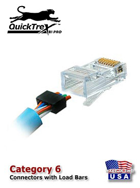
We recommend our QuickTreX connectors with load bar for the best results..
9.Check the wiring sequence one more time.
Than slide the load bar down all the way and make a straight cut about 0.25 past the loadbar.
A perfectly straight cut is essential here.
That is why we strongly recommend our new QuickTreX Wire Surgeon Electricians Scissors.
10.Insert the connector onto the load bar assembly.
Hold the plug with the copper connectors up and the locking clip facing down.
In this configuration, the Brown Pair of wires should be to the right side
11.For Crimping we recommend our QuickTreX Ratchet Crimper for RJ-45 and RJ-11/12..
Push the connector all of the way in and then squeeze down all the way on the crimper.
Remove the connector from the crimper body.
12.Slide the boots if used all the way up to the
If necessary, use a tapping motion as shown in the illustration.
13.Repeat the procedure on the other end of the cable using the same wiring diagram. NOTE: If you wish to make a crossover cable, than use the other diagram in this case 568-A
14.Test the cable using a high quality four pair tester.
For this we recommend our LANTEST-PRO Cable Tester.Notes Regarding Making Category 5 Patch Cable
1 The RJ-45 plugs are normally made for either solid conductors or stranded conductors. It is very important to be sure that the plug that you use matches the conductor type. It is extremely difficult to tell the difference between the two by looking at them. When you buy these plugs, be sure to categorize, and store them carefully. Using the wrong type can cause intermittent problems. The QuickTreX Category 5E, 8 Conductor Modular Plugs, OR QuickTreX Category 6, 8 Conductor Modular Plugs that we sell are rated for both Solid and Stranded cable.
2 Ordinarily, it would be taboo to untwist the pairs of any category 5 or 6 cable. The one exception to this rule is when crimping on RJ-45 plugs. It would be impossible to insert the wires into the channels without first untwisting and straightening them. Be sure not to extend the un-twisting, past the skin point. If you do it properly, you will wind up with no more than 1/2 of untwisted conductors up to 1/2 of untwist meets the cat 5 or 6 specification.
3 If the completed assembly does not pass continuity, you may have a problem in one, or both ends. First try giving each end another crimp. If that does not work, then carefully examine each end. Are the wires in the proper order. Do all of the wires fully extend to the end of the connector. Are all of the pins pushed down fully. Cut off the suspected bad connector, and re-terminate it. If you still have a problem, then repeat the process, this time giving more scrutiny to the end that was not replaced.Controversies and Caveats: Category 5, 5E, and Cat 6 Patch Cables
For patch cables, 568-B wiring is by far, the most common wiring method. Virtually all pre-assembled patch cables are wired to the B standard. There is no difference in connectivity between 568B and 568A cables. Therefore, a 568B patch cable should work fine on a 568A cabling system, and visa-versa.
We have seen this happen time and time again. Perfectly good patch cables that have been working fine for years, get removed from their installation, and re-installed on the same, or different network. The result can be a nightmare. What happens is that the cable, over time, adapts to the way that it is bent in it s original installation. When these cables are removed and re-installed, they can either completely lose their connection, or develop intermittent problems. This is due to stresses that may be opposite to what they were originally subject to. If the integrity of your network is more valuable than the price of new patch cables, then we strongly suggest that you use brand new cables for all closet cleanups, network moves, etc.
Almost all patch cables that are made have stranded wire. Stranded wire is normally specified for use in patch cables due to its superior flexibility. There has been some talk recently, in the technical sector of the structured wiring community, regarding the possible use of solid conductors for patch cables. The reason for the spotlight on solid wire is that it is supposedly more stable, under a variety of conditions. Please note that we now offer custom Solid copper category 5E patch cables in Plenum insulation in lengths of up to 295 feet. These cables are suitable for use in air handling Plenum ceilings and environments.Featured Product.
QuickTreX Wire Surgeon Electricians Scissors
Crafted in Germany of durable ice-tempered Solingen stainless steel that holds up under extreme use.
This wire shear is precision designed for clean cutting and specially ground for use with wire, braiding, etc.
Slight serrations on the blade prevent wire slippage and make dependable precise cuts possible.
The ergonomically designed soft rubber handle provides fatigueless use suitable for right or left-handed people.
Whether you are a professional or amateur, you will agree that these are the best wire cutting scissors that you have ever used..
Usually ships within 1 to 2 days.
We have all the plugs and the boots that you ll need to make your own cable.
very best tools, testers and toolkits
for installing and troubleshooting
The information on this page is an original copyrighted article. We welcome you to link this page from your website. However, copying this article in whole or in part is strictly prohibited.
Disclaimer: We have provided this article as general installation advice to our customers. We make no claims about the completeness or the accuracy of the information as it may apply to an infinite amount of field conditions. It is the responsibility of the person or persons using this information to check with all concerned parties, owners and local authorities, etc. before doing an installation. Users of this information agree to hold Atcom Inc. harmless form liabilities of any kind relating to the use of this information.
- questions for existing customers, or pertaining to pending sales
any others may be charged a consulting fee.

How to Make a Category 5 /5e Patch Cable
Category 5 cable, commonly referred to as cat 5, is a twisted pair cable for carrying signals. This type of cable is used in structured cabling for computer networks.

How to wire your own ethernet cables and connectors. What You Need: Required: Ethernet Cable - bulk Category Cat 5, 5e, 6, 6a or higher ethernet cable.
It is now not only possible but also easy to field terminate category 6 modular plugs thanks to the new QuickTreX QC-0808LB16-34 Category 6 modular plug which contains a new Patented Conductive NEXT Reduction System. The Conductor Loading Bar is molded from a material that substantially reduces the affect of NEXT within the Plug Body. The conductors are isolated by plastic that absorbs the NEXT from between the conductors and channels it away so that the Plug can perform to Category 6 levels. When assembled onto Category 6 compliant patch cable it will pass all TIA/EIA requirements for NEXT and Return Loss. This will help your Category 6 channel maintain increased headroom to assure your network operates at its best.
LANshack.com was the very first ecommerce website to offer free online tutorials for cable connections. To say that our articles have been popular over the span of many years would be an understatement. But time marches on and we now have three major updates. For one, we have updated this very popular tutorial, and two, we now have a video tutorial to go with it. But most importantly, we have now developed a totally new system for termination cables called the QuickTreX System
Wow. After over 10 Years of working with cables, tools and connectors, and after keeping on top of our tool, cable, and connector suppliers, we have put it all together to formulate this system for the present a future of cabling components. What does all this mean to the consumer. Compatibility, Reliability, Dependability, ease of use and virtually fool-proof and repeatable results.
Due to an overwhelming response to our category 5 6 tutorial, and many requests for information and wiring diagrams of straight through and crossover cross-pinned patch cords, I have made this informational page and technical video. On this page, we will cover making patch cords, and other technical and non-technical issues relating to category 5 and 6 patching and connectivity from device to device. Below, you will find the diagrams for 568A, 568B, and crossover patch cables. I suggest that you read on, past the diagrams for some very useful and important information.
As always, there continues to be Controversies over standards and practices regarding the use and making of patch cords, and UTP cable in general. Please see our section below titled: Controversies and Caveats : Category 5, 5E, and Cat 6 Patch Cables. I hope that you will find it interesting and informative.
Notes for wiring diagrams above:
1. For patch cables, 568-B wiring is by far, the most common method.
2. There is no difference in connectivity between 568B and 568A cables. Either wiring should work fine on any system. see notes below
3. For a straight through cable, wire both ends identical.
4. For a crossover cable, wire one end 568A and the other end 568B.
5. Do not confuse pair numbers with pin numbers. A pair number is used for reference only eg: 10BaseT Ethernet uses pairs 2 3. The pin numbers indicate actual physical locations on the plug and jack.
Patch Cable Assembly Instructions
1. Cut the cable to the length that you will need.
If you are planning to use boots, this would be a good time to slip them on.
Place each boot facing out on the cable.
2. Skin the cable about 1.5down.
For fast and dependable skinning we recommend our QuickTreX EZ Cable stripper.
3. Remove all of the twists in the cables pairs.
TEC-TIP: Use a piece of the removed insulation to make it easy to remove the twists from each pair.
Un-twist each pair, and straighten each wire between the fingers.
4. Cat 6 cable has a center spine that needs to be removed.
Pull on the spine and fold the pairs back.
Then cut the spine as close to the cables end as possible.
5. Place the wires in the order of one of the two diagrams shown above 568B or 568A.
Here we have chosen the 568B diagram which is by far the most popular.
If you are unsure, go with the 568B wiring.
6.Bring all of the wires together, until they touch.
Hold the grouped and sorted wires together tightly, between the thumb, and the forefinger.
At this point, recheck the wiring sequence with the diagram.
7.TEC-TIP: Cut the wires on a very sharp angle to make it easier to install the load-bar in the next step.
8.Insert the loadbar on the wires one wire at a time.
This is why we recommended cutting the wires on an angle.
We recommend our QuickTreX connectors with load bar for the best results..
- This great tutorial from LANshack.com goes step by step with pictures on how to terminate a Cat 5 patch cable and includes a how to video as well.
- How to Make Cat 5 / 5e Patch Cables DIY article. All the information you should need to build straight through Cat 5 Patch Cables and Crossover Cat 5 Patch Cables.
- Ethernet Patch Cord Wiring connections use wire pairs 2 and 3 to transmit and receive information, For an example of a crossover patch cable, the diagram in.
How to Make a Category 6 Patch Cable Due to an overwhelming response to our category 5 6 tutorial, and many requests for information and wiring diagrams of.
County Paramedic Patch
LA County Paramedic Patch / Size 4 3/4 x 3 3/4
Providing Quality Merchandise and Service To Those That Protect And Serve Our Communities.

Up for sale is a County of Los Angeles Fire Dept. This is a NEW full size regulation patch. As seen on the TV show EMERGENCY. . A must for all collectors.
Hillsborough, NJ -- Paramedic James V. Maguire died on Monday, Dec. 7 in the line of duty after responding to a call near his home on Sunday afternoon.

Find great deals on eBay for paramedic patch tactical paramedic. Shop with confidence.

LA County Paramedic Patch 4 3/4 x 3 3/4 THE FIRE CONNECTION Providing Quality Merchandise and Service To Those That Protect And Serve Our Communities.


Paramedic Services EMS Week 2013. Bruce County EMS is proud to celebrate EMS Week May 19th - 25th. New Look For Bruce EMS Ambulances. In 2010 Bruce County.
Alameda County Paramedic California 79 views Scan By: PatchGallery.com: San Bernardino County Paramedic Patch California 215 views Scan From: Our Collection.
Los Angeles County Fire Department Paramedic Patch California Scan From: Our Collection.
High Quality, Fully Embroidered Los Angeles County Paramedic Fire Dept Patch. Patches are for collection purposes only. This patch is in NEW condition.
Home US Fire Patches California
img src class strip_image border 0 alt Los-Angeles-County-Fire-Department-Dept-LACOFD-Mechanic-Patch-California-Patches-CAFr.jpg title Filename Los-Angeles-County-Fire-Department-Dept-LACOFD-Mechanic-Patch-California-Patches-CAFr.jpg
img src class strip_image border 0 alt Los-Angeles-County-Fire-Department-Dept-LACOFD-Ocean-Lifeguard-Patch-California-Patches-CAFr.jpg title Filename Los-Angeles-County-Fire-Department-Dept-LACOFD-Ocean-Lifeguard-Patch-California-Patches-CAFr.jpg
img src class strip_image border 0 alt Los-Angeles-County-of-Fire-Dept-Paramedic-Patch-v3-California-Patches-CAFr.jpg title Filename Los-Angeles-County-of-Fire-Dept-Paramedic-Patch-v3-California-Patches-CAFr.jpg
img src class strip_image middlethumb border 0 alt Los-Angeles-County-of-Fire-Dept-Paramedic-Patch-v2-California-Patches-CAFr.jpg title Filename Los-Angeles-County-of-Fire-Dept-Paramedic-Patch-v2-California-Patches-CAFr.jpg
img src class strip_image border 0 alt Los-Angeles-County-of-Fire-Dept-Paramedic-Patch-v1-California-Patches-CAFr.jpg title Filename Los-Angeles-County-of-Fire-Dept-Paramedic-Patch-v1-California-Patches-CAFr.jpg
img src class strip_image border 0 alt Los-Angeles-County-Fire-Department-Dept-LA-Co-FD-Quint-187-Patch-California-Patches-CAFr.jpg title Filename Los-Angeles-County-Fire-Department-Dept-LA-Co-FD-Quint-187-Patch-California-Patches-CAFr.jpg
img src class strip_image border 0 alt LA_Co__Special_Operations_Rescue.jpg title Filename LA_Co__Special_Operations_Rescue.jpg
Filename:Los-Angeles-County-of-Fire-Dept-Paramedic-Patch-v2-California-Patches-CAFr.jpg
Anonymous comments are not allowed here. Log in to post your comment
Powered by Coppermine Photo Gallery.
Our best breaking news, stories, and events from the Patch network of local news sites.
Army Apft Patch Nsn
Army Improved Physical Fitness Uniform IPFU NSN s. T-SHIRT, ATHLETES LS: XS: 8415-01-465-7362: EA: T-SHIRT, ATHLETES LS: M: 8415-01-465-7363: EA.
Aug 12, 2014 The Army s new physical fitness uniform will replace the U.S. military installations are no longer allowing visitors to gain base access using.
This question has been answered here: pt-badge-nsn-t203.html
-----------------------------------
Don t exhaust yourself looking for ah NSN for the Army Physical Fitness Badge than can be worn on the PT uniform. The badge is authorized by AR 600-8-22, Military Awards. In FED LOG s Army Interactive, the item name is BADGE, QUALIFICATION, and its nomenclature BDG QUAL ARMY PHY FIT. The NSN is 8455-01-247-0000.
6 hours ago - Army pt patch nsn U nas możesz kupić kaski motocyklowe, ubiory, mufki, motokoce i inne akcesoria do przedłużania sezonu. Sprawdź.
Apr 14, 2009 - Don t exhaust yourself looking for ah NSN for the Army Physical Fitness Badge than can be worn on the PT uniform. The badge is authorized by New NSN s - Page 3312 Nov 2010PT Badge NSN. : New NSN s10 Jul 2008More results from www.armyproperty.comwhat is the NSN for the ARMY physical fitness badge. Yahoo Answershttps://answers.yahoo.com/question/index.qidCachedSimilarMay 2, 2009 - Best Answer: The NSN is 8455-01-247-0000. Source s : US Army SFC. Shock and Awe 7 years Army Physical Fitness Badge Question.
Joint First-Aid Kit JFAK, NSN 6545-01-643-8543, Without Tourniquets
Joint First-Aid Kit JFAK, NSN 6545-01-632-0167, Complete With Tourniquets
U.S. Army Improved First Aid Kit IFAK, NSN 6545-01-584-1582, MultiCam OCP
MOLLE Rifleman Set, RFI Issue, MultiCam OCP, NSN 8465-01-580-0481, with Tactical Assault Panel TAP
RECEIVER TRANSMITTERSBravoCooktreatmentTrucks.
Click the button below to add the Jogalite Drill Sergeant Running Vest w/Army Patch Blue/Yellow to your wish list.
Oct 28, 2015 Video embedded Requirements for Army Physical Fitness Test APFT Description; Wear of the Uniform by Army Retirees and Veterans; Army Badges.
ACUArmy.com. Home; Log In; My Account. Army Service Pride Commemorative Medals: Custom Army Digital Skill Badge Cap: Custom Hats - Combat Patch Cap.
Army physical fitness patch nsn. Download. Drill sergeant running vest w/ army patch gamercompu. Physical fitness badge wikipedia, the free encyclopedia.
ArmyProperty.com
The United States Army Physical Fitness Badge is awarded to soldiers who obtain a score of 270 or higher, with a score of 90 or above in each event, on the.
Nvidia G72 Driver Download Xp
NVIDIA GeForce DDR Free Driver Download
Nvidia G72 Windows Xp Driver. Feature Requests : Navidao: NVIDIA G72 Drivers Download Description: NVIDIA G72 Driver Installer File Version: 8.4 File Size.
Description: NVIDIA G72 CnBeta Tweak For Nvidia 4.0 Driver Installer; File Version: 8.5; XP; Download Now. Share us. Tweet; Knowledge Base. What is a Windows driver.
Windows XP/2000 Driver Archive; Relevant 2006: Updated driver to include NVIDIA SLI profiles for Battlefield there is no need to download this updated kit.
Use DriverGuide s Installer what s this
Video Tutorial: How to Download Install a Driver
I try to download Nvidia GeForce Go 6150 for HP TX laptop series graphic cards,but none of them works for me, so i edit this version by myself. it will works 100 with Windows XP
Hossein DG Member on 7/27/2008
4 of 5 people found the following review helpful:
Already tried it. Give your review
Recent Discussion on NVIDIA Display / Monitor Drivers
nVIDIA SONY VGN-S38GP DISPLAY DRIVER Windows 7 PCI / ISA 1 reply
nVIDIA ge2mx40064spci Windows XP Home PCI / ISA 1 reply
nVIDIA NVIDIA geforce4 mx420 Windows XP Professional PCI / ISA 1 reply
nVIDIA t3256 Windows XP Professional IDE 1 reply
nVIDIA AX-84GS/256D2P4CDHTL Windows XP Professional PCI / ISA 1 reply
Premium Member DRIVER NEEDED: nVIDIA GeForce8400GS Windows Vista PCI / ISA 1 reply
nVIDIA slv3-t1128d Windows XP Professional 1 reply
Premium Member DRIVER NEEDED: nVIDIA Standard AHCI 1.0 Serial ATA Controller 6.1.7601.17514 Windows 7 PCI / ISA 1 reply
NVIDIA GF2MX400 Windows XP Professional IDE 1 reply
nVIDIA nVIDIA GeForce2 MX/MX400 Windows Vista PCI / ISA 1 reply
nVIDIA geforce 2 mx/mx400 Windows XP Professional 1 reply
nVIDIA VGA Save for HP D530 SFF DC578AV Windows XP Home 1 reply
nVIDIA fx 5500 Windows XP Home IDE 1 reply
nVIDIA Ge Force 2 Windows XP Professional IDE 1 reply
nVIDIA gforce 7300 gs Windows XP Professional PCMCIA 1 reply
nVIDIA Geforce fx go5200 Windows XP Home 1 reply
nVIDIA ax-94gt Windows XP Home PCI / ISA
nvidia tnt2 m64 Windows XP Professional PCI / ISA 1 reply
nVIDIA nvidia riva tnt2 model 64 Windows XP Professional 1 reply
Video nvidia g72 driver version a01 free download - nVidia Detonator Driver Win 2000/XP, MSI nVidia-based Graphics Drivers Windows 2000/XP, nVidia WDM Driver.

Here you can download free drivers for NVIDIA G72. Operacinė sistema: 2000 XP W2k3 Vista W7 W8 W8.1 W10. Vairuotojo data: 2004-01-01. Versija: 9.3.7.1.
- Nvidia g72 free download - nVidia Graphics Driver Windows Vista 32-bit / Windows 7 32-bit / Windows 8 32-bit, nVidia Graphics Driver Windows XP/Media Center.
- Official Nvidia g72 drivers download, download and update your Nvidia g72 drivers for Windows XP, Vista, nvidia g72 Driver Download.
- Download nvidia g72 drivers ez93.com. Nvidia G72 Windows 8.1 Restore Disk : Operating System Windows 8.1 Drivers.
Bytecc Me - 320 X Driver
Get the Bytecc ME-320 Driver from our web site absolutely free of charge. The computer drivers from Bytecc are located through the web links above.

BT-RS232 Driver For Win98 XP USB1.1 to SERIAL/RS-232 Adapter Cable
BT-200 Driver USB 2.0 to IDE Adapter / BT-200 Help
BT-300 Driver USB 2.0 to IDE/SATA Adapter
UL-200 Driver USB2.0 Data Transfer Cable
ME-705, ME-720, ME-740, ME-340, PG-380 USB2.0 Driver
USB-1284 Driver USB1.1 to Parallel/IEEE-1284 Adapter Cable
ME-850 Landisk Firmware Update Ver 0.24
ME-850 Landisk FTP Server Setup Help
ME-850 LANDISK Vista Support Setup Help
BT-DB925 Driver USB1.1 to RS232 Adapter Cable Windows, MAC, Linux
ME-808 BackupStar new version software only
BT-380NAS beta driver for Windows Vista, 32-bit version
BT-618 Driver 42in1 Card Reader Hub
BT-380NAS beta driver for Windows Vista, 64-bit version
ALI TH07 Chipset ME-720U2, ME-740U2, ME-320U2
Prolific PL-3507 Chipset ME-320U2F, ME-340U2F, ME-705U2F, ME-720U2F, ME-740U2F
MCK-8800 Eagle Touch Wireless Keyboard Driver
MCK-8800 Eagle Touch Wireless Mouse Driver
BT-PE1S Driver for PCIe Serial Card 1 Port
SKB-2200 Eagle Touch USB Slim Multimedia Keyboard
BT-PE2S Driver for PCIe Serial Card 2 Ports
BT-PE1P Driver for PCIe Parallel Card 1 Port
U2FW-CB-4 Driver USB2.0 4 Ports PCMCIA Card
BT-PE2P Driver for PCIe Parallel Card - 2 ports
BT-144 Driver USB External Floppy Disk
BT-PE2S1P Driver for PCIe Serial 2 Ports Parallel 1 Port Card
BT-P2S Driver 2 Serial Ports PCI Card DOS, Linux, Windows
BT-PESAPA Driver for PCIe SATA II 300 PATA Raid Card
VUP-215 Driver Advance VoIP USB Cellular size Phone
ST-109 Driver Serial ATA 2 Ports PCMCIA Card
Copyright c 2007 Bytecc Inc. All Rights Reserved.
Bytecc me 320 x driver. Posted: slipel On: 29.06.2015. Filename: Bytecc me 320 x driver File size: 2 MB / Total downloads: 2014. Next, the application is free.
Working keygen adobe cs3 master suite Bytecc ME-320x USB 2.0 External Enclosure. Following the manuals instructions and installing the drivers first before hooking up.

Bytecc USB Storage Adapter AT2 CY Free Driver Download for Windows 98SE - Bytecc-USB-ME-320-X.zip. World s most popular driver download site.

External subsystem ME-320x. Tags: search engine. Gene Beach July 12, 2011 at :06 Specs: Windows Vista. I have a Bytecc ME-320x apparently manufactured.
Bytecc Driver. File Contents: List of all Bytecc Drivers. BIOS Graphics/Video Input Network Sound Card USB.
Here you can download BYTECC ME-320U2F driver for. For ME-320U2F BYTECC Accessories Nodevice offers more than one driver for free download. How to install.
Bytecc ME-320x USB 2.0 External The Bytecc ME-320 series is just one of many that Bytecc Following the manuals instructions and installing the drivers first.
Sample Device Driver Code In C

How to Create a Device Driver The sample driver code demonstrated in the following steps is merely a starting point and does not actually work with specific.
How to write a simple Linux device driver. I am going through spi-omap2-mcspi.c code as reference to get an idea to Checking simple char device read/write.
Rename the code example files . c, To build the sample driver downloaded in the previous section a reference the recently loaded device driver should be listed.
Download source files - 10.4 Kb
This tutorial will attempt to describe how to write a simple device driver for Windows NT. There are various resources and tutorials on the internet for writing device drivers, however, they are somewhat scarce as compared to writing a hello world GUI program for Windows. This makes the search for information on starting to write device drivers a bit harder. You may think that if there s already one tutorial, why do you need more. The answer is that more information is always better especially when you are first beginning to understand a concept. It is always good to see information from different perspectives. People write differently and describe certain pieces of information in a different light depending on how familiar they are with a certain aspect or how they think it should be explained. This being the case, I would recommend anyone who wants to write device drivers not to stop here or somewhere else. Always find a variety of samples and code snippets and research the differences. Sometimes there are bugs and things omitted. Sometimes there are things that are being done that aren t necessary, and sometimes there s information incorrect or just incomplete.
This tutorial will describe how to create a simple device driver, dynamically load and unload it, and finally talk to it from user mode.
Creating a Simple Device Driver
I need to define a starting ground before we begin to explain how to write a device driver. The starting point for this article will be the compiler. The compiler and linker generate a binary in a format that the Operating System understands. In Windows, this format is PE for Portable Executable format. In this format, there is an idea called a subsystem. A subsystem, along with other options specified in the PE header information, describes how to load an executable which also includes the entry point into the binary.
Many people use the VC IDE to simply create a project with some default pre-set options for the compiler s and linker command line. This is why a lot of people may not be familiar with this concept even though they are most likely already using it if they have ever written Windows applications. Have you ever written a console application. Have you ever written a GUI application for Windows. These are different subsystems in Windows. Both of these will generate a PE binary with the appropriate subsystem information. This is also why a console application uses main where a WINDOWS application uses WinMain. When you choose these projects, VC simply creates a project with /SUBSYSTEM:CONSOLE or /SUBSYSTEM:WINDOWS. If you accidentally choose the wrong project, you can simply change this in the linker options menu rather than needing to create a new project.
There s a point to all of this. A driver is simply linked using a different subsystem called NATIVE. MSDN Subsystem compiler options.
After the compiler is setup with the appropriate options, it s probably good to start thinking about the entry point to a driver. The first section lied a little bit about the subsystem. NATIVE can also be used to run user-mode applications which define an entry point called NtProcessStartup. This is the default type of executable that is made when specifying NATIVE in the same way WinMain and main are found when the linker is creating an application. You can override the default entry point with your own, simply by using the -entry: linker option. If we know we want this to be a driver, we simply need to write an entry point whose parameter list and return type matches that of a driver. The system will then load the driver when we install it and tell the system that it is a driver.
The name we use can be anything. We can call it BufferFly if we want. The most common practice used by driver developers and Microsoft is using the name DriverEntry as its initial entry point. This means we add -entry:DriverEntry to the linker s command line options. If you are using the DDK, this is done for you when you specify DRIVER as the type of executable to build. The DDK contains an environment that has pre-set options in the common make file directory which makes it simpler to create an application as it specifies the default options. The actual driver developer can then override these settings in the make file or simply use them as a connivance. This is essentially how DriverEntry became the somewhat official name for driver entry points.
Remember, DLLs actually are also compiled specifying WINDOWS as the subsystem, but they also have an additional switch called /DLL. There is a switch which can also be used for drivers: /DRIVER:WDM which also sets NATIVE behind the scenes as well as a /DRIVER:UP which means this driver cannot be loaded on a multi-processor system.
The linker builds the final binary, and based on what the options are in the PE header and how the binary is attempting to be loaded run as an EXE through the loader, loaded by LoadLibrary, or attempting to be loaded as a driver will define how the loading system behaves. The loading system attempts to perform some level of verification, that the image being loaded is indeed supposed to be loaded in this manner, for example. There is even, in some cases, startup code added to the binary that executes before your entry point is reached WinMainCRTStartup calling WinMain, for example, to initialize the CRT. Your job is to simply write the application based on how you want it to be loaded and then set the correct options in the linker so it knows how to properly create the binary. There are various resources on the details of the PE format which you should be able to find if you are interested in further investigation into this area.
The options we will set for the linker will end up being the following:/SUBSYSTEM:NATIVE /DRIVER:WDM –entry:DriverEntry
Before creating the DriverEntry
There are some things we need to go over before we simply sit down and write the DriverEntry. I know that a lot of people simply want to jump right into writing the driver and seeing it work. This is generally the case in most programming scenarios as you usually just take the code, change it around, compile it, and test it out. If you remember back to when you were first learning Windows development, it was probably the same way. Your application probably didn t work right away, probably crashed, or just disappeared. This was a lot of fun and you probably learned a lot, but you know that with a driver, the adventure is a little different. Not knowing what to do can end up in blue screening the system, and if your driver is loaded on boot and executes that code, you now have a problem. Hopefully, you can boot in safe mode or restore to a previous hardware configuration. That being the case, we have a few things to go over before you write the driver in order to help educate you on what you are doing before you actually do it.
The first rule of thumb is do not just take a driver and compile it with some of your changes. If you do not understand how the driver is working or how to program correctly in the environment, you are likely to cause problems. Drivers can corrupt the integrity of the whole system, they can have bugs that don t always occur but in some rare circumstances. Application programs can have the same type of bugs in behavior but not in root cause. As an example, there are times when you cannot access memory that is pagable. If you know how Virtual Memory works, you know that the Operating System will remove pages from memory to pull in pages that are needed, and this is how more applications can run than would have been physically possible given the memory limitations of the machine. There are places, however, when pages cannot be read into memory from disk. At these times, those drivers who work with memory can only access memory that cannot be paged out.
Where am I going with this. Well, if you allow a driver which runs under these constraints to access memory that is pagable, it may not crash as the Operating System usually tries to keep all pages in memory as long as possible. If you close an application that was running, it may still be in memory, for example. This is why a bug like this may go undetected unless you try doing things like driver verifier and eventually may trap. When it does, if you do not understand the basic concepts like this, you would be lost as to what the problem is and how to fix it.
There are a lot of concepts behind everything that will be described in this document. On IRQL alone, there is a twenty page document you can find on MSDN. There s an equally large document on IRP. I will not attempt to duplicate this information nor point out every single little detail. What I will attempt to do is give a basic summary and point you in the direction of where to find more information. It s important to at least know that these concepts exist and understand some basic idea behind them, before writing the driver.
The IRQL is known as the Interrupt ReQuest Level. The processor will be executing code in a thread at a particular IRQL. The IRQL of the processor essentially helps determine how that thread is allowed to be interrupted. The thread can only be interrupted by code which needs to run at a higher IRQL on the same processor. Interrupts requiring the same IRQL or lower are masked off so only interrupts requiring a higher IRQL are available for processing. In a multi-processor system, each processor operates independently at its own IRQL.
There are four IRQL levels which you generally will be dealing with, which are Passive, APC, Dispatch and DIRQL. Kernel APIs documented in MSDN generally have a note which specifies the IRQL level at which you need to be running in order to use the API. The higher the IRQL you go, the less APIs that are available for use. The documentation on MSDN defines what IRQL the processor will be running at when the particular entry point of the driver is called. DriverEntry, for example, will be called at PASSIVE_LEVEL.
This is the lowest IRQL. No interrupts are masked off and this is the level in which a thread executing in user mode is running. Pagable memory is accessible.
In a processor running at this level, only APC level interrupts are masked. This is the level in which Asynchronous Procedure Calls occur. Pagable memory is still accessible. When an APC occurs, the processor is raised to APC level. This, in turn, also disables other APCs from occurring. A driver can manually raise its IRQL to APC or any other level in order to perform some synchronization with APCs, for example, since APCs can t be invoked if you are already at APC level. There are some APIs which can t be called at APC level due to the fact that APCs are disabled, which, in turn, may disable some I/O Completion APCs.
The processor running at this level has DPC level interrupts and lower masked off. Pagable memory cannot be accessed, so all memory being accessed must be non-paged. If you are running at Dispatch Level, the APIs that you can use greatly decrease since you can only deal with non-paged memory.
Generally, higher level drivers do not deal with IRQLs at this level, but all interrupts at this level or less are masked off and do not occur. This is actually a range of IRQLs, and this is a method to determine which devices have priority over other devices.
In this driver, we will basically only be working at PASSIVE_LEVEL, so we won t have to worry about the gotchas. However, it is necessary for you to be aware of what IRQL is, if you intend to continue writing device drivers.
For more information on IRQLs and thread scheduling, refer to the following documentation, and another good source of information is here.
The IRP is called the I/O Request Packet, and it is passed down from driver to driver in the driver stack. This is a data structure that allows drivers to communicate with each other and to request work to be done by the driver. The I/O manager or another driver may create an IRP and pass it down to your driver. The IRP includes information about the operation that is being requested.
A description of the IRP data structure can be found here.
The description and usage of an IRP can go from simple to complex very easily, so we will only be describing, in general, what an IRP will mean to you. There is an article on MSDN which describes in a lot more detail about twenty pages of what exactly an IRP is and how to handle them. That article can be found here.
The IRP will also contain a list of sub-requests also known as the IRP Stack Location. Each driver in the device stack will generally have its own sub request of how to interpret the IRP. This data structure is the IO_STACK_LOCATION and is described on MSDN.
To create an analogy of the IRP and IO_STACK_LOCATION, perhaps you have three people who do different jobs such as carpentry, plumbing and welding. If they were going to build a house, they could have a common overall design and perhaps a common set of tools like their tool box. This includes things like power drills, etc. All of these common tools and overall design of building a house would be the IRP. Each of them has an individual piece they need to work on to make this happen, for example, the plumber needs the plans on where to put the pipe, how much pipe he has, etc. These could be interpreted as the IO_STACK_LOCATION as his specific job is to do the piping. The carpenter could be building the framework for the house and the details of that would be in his IO_STACK_LOCATION. So, while the entire IRP is a request to build a house, each person in the stack of people has their own job as defined by the IO_STACK_LOCATION to make this happen. Once everyone has completed their job, they then complete the IRP.
The device driver we will be building will not be that complex and will basically be the only driver in the stack.
There are a lot of pitfalls that you will need to avoid but they are mostly unrelated to our simple driver. To be more informed, however, here is a list of items called things to avoid when it comes to driver development.
Create the DriverEntry routine
There is so much to explain, however, I think it s time we simply started to develop the driver and explain as we go. It is hard to digest theory or even how code is supposed to work, without actually doing anything. You need some hands on experience so you can bring these ideas out of space and into reality.
The prototype for the DriverEntry is the following.NTSTATUS DriverEntry PDRIVER_OBJECT pDriverObject, PUNICODE_STRING pRegistryPath ;
The DRIVER_OBJECT is a data structure used to represent this driver. The DriverEntry routine will use it to populate it with other entry points to the driver for handling specific I/O requests. This object also has a pointer to a DEVICE_OBJECT which is a data structure which represents a particular device. A single driver may actually advertise itself as handling multiple devices, and as such, the DRIVER_OBJECT maintains a linked list pointer to all the devices this particular driver services request for. We will simply be creating one device.
The Registry Path is a string which points to the location in the registry where the information for the driver was stored. The driver can use this location to store driver specific information.
The next part is to actually put things in the DriverEntry routine. The first thing we will do is create the device. You may be wondering how we are going to create a device and what type of device we should create. This is generally because a driver is usually associated with hardware but this is not the case. There are a variety of different types of drivers which operate at different levels, not all drivers work or interface directly with hardware. Generally, you maintain a stack of drivers each with a specific job to do. The highest level driver is the one that communicates with user mode, and the lowest level drivers generally just talk to other drivers and hardware. There are network drivers, display drivers, file system drivers, etc., and each has their own stack of drivers. Each place in the stack breaks up a request into a more generic or simpler request for the lower level driver to service. The highest level drivers are the ones which communicate themselves to user mode, and unless they are a special device with a particular framework like display drivers, they can behave generally the same as other drivers just as they implement different types of operations.
As an example, take the hard disk drive. The driver which communicates to user mode does not talk directly to hardware. The high level driver simply manages the file system itself and where to put things. It then communicates where it wants to read or write from the disk to the lower level driver which may or may not talk directly to hardware. There may be another layer which then communicates that request to the actual hardware driver which then physically reads or writes a particular sector off a disk and then returns it to the higher level. The highest level may interpret them as file data, but the lowest level driver may simply be stupid and only manage requests as far as when to read a sector based off where the read/write head is located on the disk. It could then determine what sector read requests to service, however, it has no idea what the data is and does not interpret it.
Let s take a look at the first part of our DriverEntry. NTSTATUS DriverEntry PDRIVER_OBJECT pDriverObject, PUNICODE_STRING pRegistryPath
NTSTATUS NtStatus STATUS_SUCCESS;
PDEVICE_OBJECT pDeviceObject NULL;
UNICODE_STRING usDriverName, usDosDeviceName;
DbgPrint DriverEntry Called r n ;
RtlInitUnicodeString usDriverName, L Device Example ;
RtlInitUnicodeString usDosDeviceName, L DosDevices Example ;
NtStatus IoCreateDevice pDriverObject, 0,
The first thing you will notice is the DbgPrint function. This works just like printf and it prints messages out to the debugger or debug output window. You can get a tool called DBGVIEW from www.sysinternals.com and all of the information in those messages will be displayed.
You will then notice that we use a function called RtlInitUnicodeString which basically initializes a UNICODE_STRING data structure. This data structure contains basically three entries. The first is the size of the current Unicode string, the second is the maximum size that the Unicode string can be, and the third is a pointer to the Unicode string. This is used to describe a Unicode string and used commonly in drivers. The one thing to remember with UNICODE_STRING is that they are not required to be NULL terminated since there is a size parameter in the structure. This causes problems for people new to driver development as they assume a UNICODE_STRING is NULL terminated, and they blue-screen the driver. Most Unicode strings passing into your driver will not be NULL terminated, so this is something you need to be aware of.
Devices have names just like anything else. They are generally named Device and this is the string we were creating to pass into IoCreateDevice. The second string, DosDevices Example, we will get into later as it s not used in the driver yet. To the IoCreateDevice, we pass in the driver object, a pointer to the Unicode string we want to call the driver, and we pass in a type of driver UNKNOWN as it s not associated with any particular type of device, and we also pass in a pointer to receive the newly created device object. The parameters are explained in more detail at IoCreateDevice.
The second parameter we passed 0, and it says to specify the number of bytes to create for the device extension. This is basically a data structure that the driver writer can define which is unique to that device. This is how you can extend the information being passed into a device and create device contexts, etc. in which to store instance data. We will not be using this for this example.
Now that we have successfully created our Device Example device driver, we need to setup the Driver Object to call into our driver when certain requests are made. These requests are called IRP Major requests. There are also Minor requests which are sub-requests of these and can be found in the stack location of the IRP.
The following code populates certain requests: for uiIndex 0; uiIndex IRP_MJ_MAXIMUM_FUNCTION; uiIndex
pDriverObject- MajorFunction uiIndex Example_UnSupportedFunction;
pDriverObject- MajorFunction IRP_MJ_CLOSE Example_Close;
pDriverObject- MajorFunction IRP_MJ_CREATE Example_Create;
pDriverObject- MajorFunction IRP_MJ_DEVICE_CONTROL Example_IoControl;
pDriverObject- MajorFunction IRP_MJ_READ Example_Read;
pDriverObject- MajorFunction IRP_MJ_WRITE USE_WRITE_FUNCTION;
We populate the Create, Close, IoControl, Read and Write. What do these refer to. When communicating with the user-mode application, certain APIs call directly to the driver and pass in parameters.
CloseHandle - IRP_MJ_CLEANUP IRP_MJ_CLOSE
DeviceIoControl - IRP_MJ_DEVICE_CONTROL
To explain, one difference is IRP_MJ_CLOSE is not called in the context of the process which created the handle. If you need to perform process related clean up, then you need to handle IRP_MJ_CLEANUP as well.
So as you can see, when a user mode application uses these functions, it calls into your driver. You may be wondering why the user mode API says file when it doesn t really mean file. That is true, these APIs can talk to any device which exposes itself to user mode, they are not only for accessing files. In the last piece of this article, we will be writing a user mode application to talk to our driver and it will simply do CreateFile, WriteFile, CloseHandle. That s how simple it is. USE_WRITE_FUNCTION is a constant I will explain later.
The next piece of code is pretty simple, it s the driver unload function. pDriverObject- DriverUnload Example_Unload;
You can technically omit this function but if you want to unload your driver dynamically, then it must be specified. If you do not specify this function once your driver is loaded, the system will not allow it to be unloaded.
The code after this is actually using the DEVICE_OBJECT, not the DRIVER_OBJECT. These two data structures may get a little confusing since they both start with D and end with _OBJECT, so it s easy to confuse which one we re using. pDeviceObject- Flags IO_TYPE;
pDeviceObject- Flags DO_DEVICE_INITIALIZING ;
We are simply setting the flags. IO_TYPE is actually a constant which defines the type of I/O we want to do I defined it in example.h. I will explain this in the section on handling user-mode write requests.
The DO_DEVICE_INITIALIZING tells the I/O Manager that the device is being initialized and not to send any I/O requests to the driver. For devices created in the context of the DriverEntry, this is not needed since the I/O Manager will clear this flag once the DriverEntry is done. However, if you create a device in any function outside of the DriverEntry, you need to manually clear this flag for any device you create with IoCreateDevice. This flag is actually set by the IoCreateDevice function. We cleared it here just for fun even though we weren t required to.
The last piece of our driver is using both of the Unicode strings we defined above. Device Example and DosDevices Example. IoCreateSymbolicLink usDosDeviceName, usDriverName ;
IoCreateSymbolicLink does just that, it creates a Symbolic Link in the object manager. To view the object manager, you may download my tool QuickView, or go to www.sysinternals.com and download WINOBJ. A Symbolic Link simply maps a DOS Device Name to an NT Device Name. In this example, Example is our DOS Device Name and Device Example is our NT Device Name.
To put this into perspective, different vendors have different drivers and each driver is required to have its own name. You cannot have two drivers with the same NT Device name. Say, you have a memory stick which can display itself to the system as a new drive letter which is any available drive letter such as E. If you remove this memory stick and say you map a network drive to E. Application can talk to E: the same way, they do not care if E: is a CD ROM, Floppy Disk, memory stick or network drive. How is this possible. Well, the driver needs to be able to interpret the requests and either handle them within themselves such as the case of a network redirector or pass them down to the appropriate hardware driver. This is done through symbolic links. E: is a symbolic link. The network mapped drive may map E: to Device NetworkRedirector and the memory stick may map E: to Device FujiMemoryStick, for example.
This is how applications can be written using a commonly defined name which can be abstracted to point to any device driver which would be able to handle requests. There are no rules here, we could actually map Device Example to E. We can do whatever we wish to do, but in the end, however, the application attempts to use the device as how the device driver needs to respond and act. This means supporting IOCTLs commonly used by those devices as applications will try to use them. COM1, COM2, etc. are all examples of this. COM1 is a DOS name which is mapped to an NT Device name of a driver which handles serial requests. This doesn t even need to be a real physical serial port.
So we have defined Example as a DOS Device which points to Device Example. In the communicating with usermode portion, we will learn more about how to use this mapping.
The next piece of code we will look at is the unload routine. This is required in order to be able to unload the device driver dynamically. This section will be a bit smaller as there is not much to explain.VOID Example_Unload PDRIVER_OBJECT DriverObject
UNICODE_STRING usDosDeviceName;
DbgPrint Example_Unload Called r n ;
IoDeleteSymbolicLink usDosDeviceName ;
IoDeleteDevice DriverObject- DeviceObject ;
You can do whatever you wish in your unload routine. This unload routine is very simple, it just deletes the symbolic link we created and then deletes the only device that we created which was Device Example.
The rest of the functions should be self explanatory as they don t do anything. This is why I am only choosing to explain the Write routine. If this article is liked, I may write a second tutorial on implementing the IO Control function.
If you have used WriteFile and ReadFile, you know that you simply pass a buffer of data to write data to a device or read data from a device. These parameters are sent to the device in the IRP as we explained previously. There is more to the story though as there are actually three different methods that the I/O Manager will use to marshal this data before giving the IRP to the driver. That also means that how the data is marshaled is how the driver s Read and Write functions need to interpret the data.
The three methods are Direct I/O, Buffered I/O and Neither. ifdef __USE_DIRECT__
define USE_WRITE_FUNCTION Example_WriteDirectIO
define USE_WRITE_FUNCTION Example_WriteBufferedIO
define USE_WRITE_FUNCTION Example_WriteNeither
The code was written so if you define __USE_DIRECT__ in the header, then IO_TYPE is now DO_DIRECT_IO and USE_WRITE_FUNCTION is now Example_WriteDirectIO. If you define __USE_BUFFERED__ in the header, then IO_TYPE is now DO_BUFFERED_IO and USE_WRITE_FUNCTION is now Example_WriteBufferedIO. If you don t define __USE_DIRECT__ or __USE_BUFFERED__, then IO_TYPE is defined as 0 neither and the write function is Example_WriteNeither.
We will now go over each type of I/O.
The first thing I will do is simply show you the code for handling direct I/O.NTSTATUS Example_WriteDirectIO PDEVICE_OBJECT DeviceObject, PIRP Irp
PIO_STACK_LOCATION pIoStackIrp NULL;
DbgPrint Example_WriteDirectIO Called r n ;
pIoStackIrp IoGetCurrentIrpStackLocation Irp ;
MmGetSystemAddressForMdlSafe Irp- MdlAddress, NormalPagePriority ;
if Example_IsStringTerminated pWriteDataBuffer,
pIoStackIrp- Parameters.Write.Length
The entry point simply provides the device object for the device for which this request is being sent for. If you recall, a single driver can create multiple devices even though we have only created one. The other parameter is as was mentioned before which is an IRP.
The first thing we do is call IoGetCurrentIrpStackLocation, and this simply provides us with our IO_STACK_LOCATION. In our example, the only parameter we need from this is the length of the buffer provided to the driver, which is at Parameters.Write.Length.
The way buffered I/O works is that it provides you with a MdlAddress which is a Memory Descriptor List. This is a description of the user mode addresses and how they map to physical addresses. The function we call then is MmGetSystemAddressForMdlSafe and we use the Irp- MdlAddress to do this. This operation will then give us a system virtual address which we can then use to read the memory.
The reasoning behind this is that some drivers do not always process a user mode request in the context of the thread or even the process in which it was issued. If you process a request in a different thread which is running in another process context, you would not be able to read user mode memory across process boundaries. You should know this already, as you run two applications they can t just read/write to each other without Operating System support.
So, this simply maps the physical pages used by the user mode process into system memory. We can then use the returned address to access the buffer passed down from user mode.
This method is generally used for larger buffers since it does not require memory to be copied. The user mode buffers are locked in memory until the IRP is completed which is the downside of using direct I/O. This is the only downfall and is why it s generally more useful for larger buffers.
The first thing I will do is simply show you the code for handling buffered I/O.NTSTATUS Example_WriteBufferedIO PDEVICE_OBJECT DeviceObject, PIRP Irp
DbgPrint Example_WriteBufferedIO Called r n ;
pWriteDataBuffer PCHAR Irp- AssociatedIrp.SystemBuffer;
As mentioned above, the idea is to pass data down to the driver that can be accessed from any context such as another thread in another process. The other reason would be to map the memory to be non-paged so the driver can also read it at raised IRQL levels.
The reason you may need to access memory outside the current process context is that some drivers create threads in the SYSTEM process. They then defer work to this process either asynchronously or synchronously. A driver at a higher level than your driver may do this or your driver itself may do it.
The downfall of using Buffered I/O is that it allocates non-paged memory and performs a copy. This is now overhead in processing every read and write into the driver. This is one of the reasons this is best used on smaller buffers. The whole user mode page doesn t need to be locked in memory as with Direct I/O, which is the plus side of this. The other problem with using this for larger buffers is that since it allocates non-paged memory, it would need to allocate a large block of sequential non-paged memory.
The first thing I will do is show you the code for handling neither Buffered nor Direct I/O.NTSTATUS Example_WriteNeither PDEVICE_OBJECT DeviceObject, PIRP Irp
DbgPrint Example_WriteNeither Called r n ;
pIoStackIrp- Parameters.Write.Length,
pWriteDataBuffer Irp- UserBuffer;
__except EXCEPTION_EXECUTE_HANDLER
In this method, the driver accesses the user mode address directly. The I/O manager does not copy the data, it does not lock the user mode pages in memory, it simply gives the driver the user mode address buffer.
The upside of this is that no data is copied, no memory is allocated, and no pages are locked into memory. The downside of this is that you must process this request in the context of the calling thread so you will be able to access the user mode address space of the correct process. The other downside of this is that the process itself can attempt to change access to the pages, free the memory, etc., on another thread. This is why you generally want to use ProbeForRead and ProbeForWrite functions and surround all the code in an exception handler. There s no guarantee that at any time the pages could be invalid, you can simply attempt to make sure they are, before you attempt to read or write. This buffer is stored at Irp- UserBuffer.
These directives you see simply let the linker know what segment to put the code and what options to set on the pages. The DriverEntry, for example, is set as INIT which is a discardable page. This is because you only need that function during initialization.
Your homework is to create the Read routines for each type of I/O processing. You can use the Write routines as reference to figure out what you need to do.
Dynamically Loading and Unloading the Driver
A lot of tutorials will go and explain the registry, however, I have chosen not to at this time. There is a simple user mode API that you can use to load and unload the driver without having to do anything else. This is what we will use for now.int _cdecl main void
hSCManager OpenSCManager NULL, NULL, SC_MANAGER_CREATE_SERVICE ;
hService CreateService hSCManager, Example,
SERVICE_START DELETE SERVICE_STOP,
NULL, NULL, NULL, NULL, NULL ;
hService OpenService hSCManager, Example,
SERVICE_START DELETE SERVICE_STOP ;
StartService hService, 0, NULL ;
printf Press Enter to close service r n ;
ControlService hService, SERVICE_CONTROL_STOP, ss ;
CloseServiceHandle hSCManager ;
This code will load the driver and start it. We load the driver with SERVICE_DEMAND_START which means this driver must be physically started. It will not start automatically on boot, that way we can test it, and if we blue-screen, we can fix the issue without having to boot to safe mode.
This program will simply pause. You can then run the application that talks to the service, in another window. The code above should be pretty easy to understand that you need to copy the driver to C: example.sys in order to use it. If the service fails to create, it knows it has already been created and opens it. We then start the service and pause. Once you press Enter, we stop the service, delete it from the list of services, and exit. This is very simple code and you can modify it to serve your purposes.
Communicating to the Device Driver
The following is the code that communicates to the driver.int _cdecl main void
GENERIC_READ GENERIC_WRITE, 0, NULL,
WriteFile hFile, Hello from user mode.,
sizeof Hello from user mode., dwReturn, NULL ;
This is probably simpler than you thought. If you compile the driver three times using the three different methods of I/O, the message sent down from user mode should be printed in DBGVIEW. As you notice, you simply need to open the DOS Device Name using . . You could even open Device using the same method. You will then create a handle to the device and you can call WriteFile, ReadFile, CloseHandle, DeviceIoControl. If you want to experiment, simply perform actions and use DbgPrint to show what code is being executed in your driver.
This article showed a simple example of how to create a driver, install it, and access it via a simple user mode application. You may use the associated source files to change and experiment. If you wish to write drivers, it s best to read up on many of the basic concepts of drivers, especially, some of the ones linked to in this tutorial.
Driver Development Part 1: Introduction to Drivers
1 Introduction to Device Drivers. This the bus code calls the driver s probe for a device are part of the source for a device driver. Device drivers.


File system filter development and windows driver Sample Code Windows Driver Samples SimdeviceUMDFName Sample device UMDF Driver.
Custom Windows driver Sample Code Windows Driver Samples Installation Disk DeviceDesc UMDF HID minidriver Sample Device.
This is the Virtvol sample driver. This driver basically creates a nonpaged pool and exposes that as a storage media. User can find the device in the disk manager and.
Oct 01, 2001 How to Write a Linux USB Device Driver. From Issue 90 October 2001. Sample code for linux usb device driver. Submitted by Anonymous not.